2022SummerTeam3
Team Members
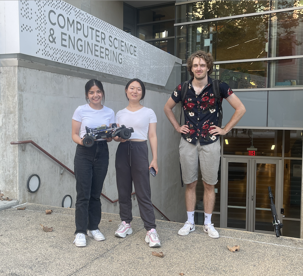
- Nachelle Matute - Computer Engineering (Left)
- Shixuan Wu - Electrical Engineering (Middle)
- Jack Hecker - Mechanical Engineering (Right)
Physical Setup
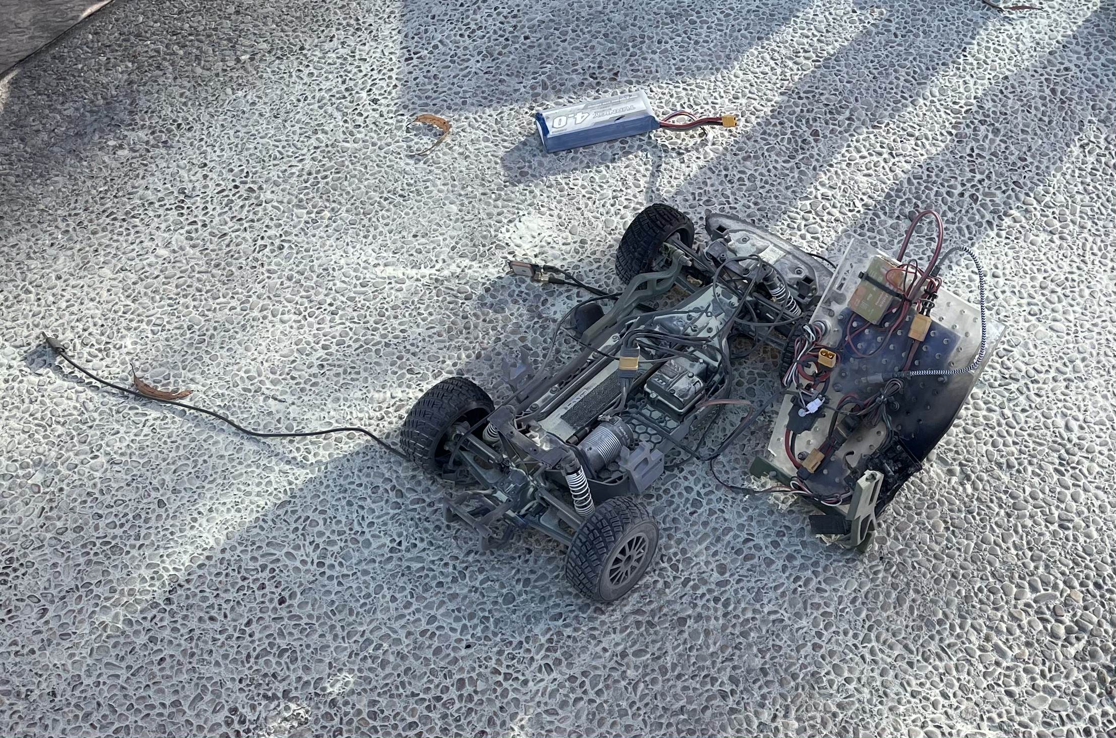
Three days before our final project was due, we were having issues with our VESC. Whilst trying to re-calibrate our VESC, it ignited, resulting in extensive damage to the car and necessitating a replacement.
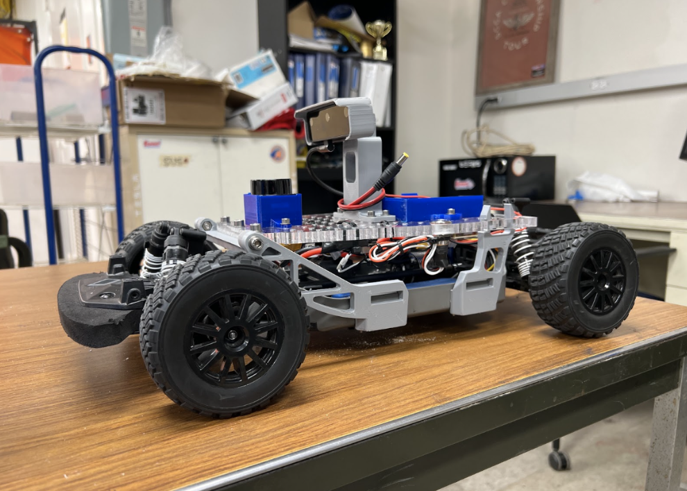
Original Car
Damaged Car
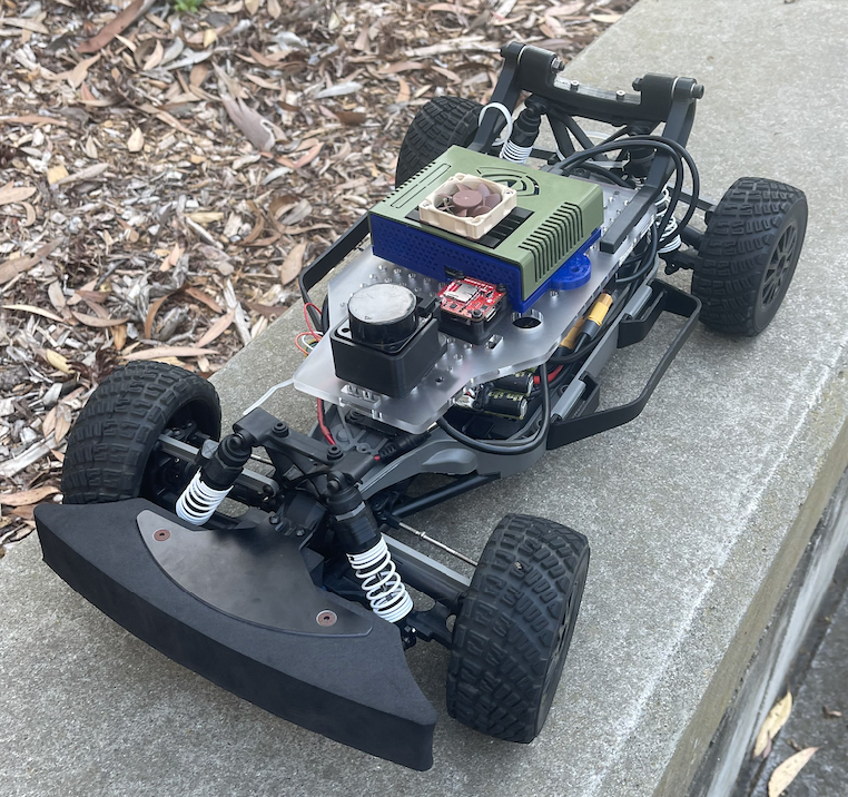
New Car
Original Car Mechanical Design
Considerations/Goals
- Maximize component envelope
- Standardize mounting system for modular packaging
- Accessibility/Serviceability
- Integration into provided chassis
- Aesthetics
Design Features
- Acrylic component bed with forward hinge for serviceability
- Locating points spaced at 15mm in x and y directions
- Buckle-type fastening at rear corners for ease of use
- 3D printed PLA structural members mounted to vehicle chassis
- Trapped-nut features on clearance holes for serviceability
- OAKD Camera, Jetson Nano, and LIDAR bolted to upper surface, other components cable-tied to underside
Part Drawings
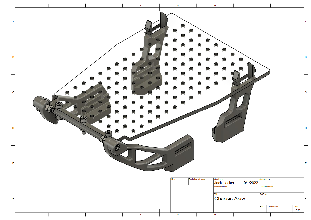
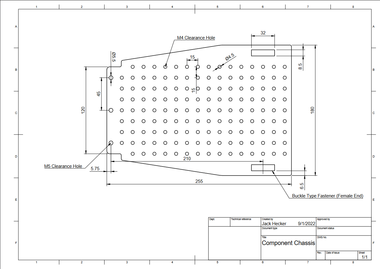
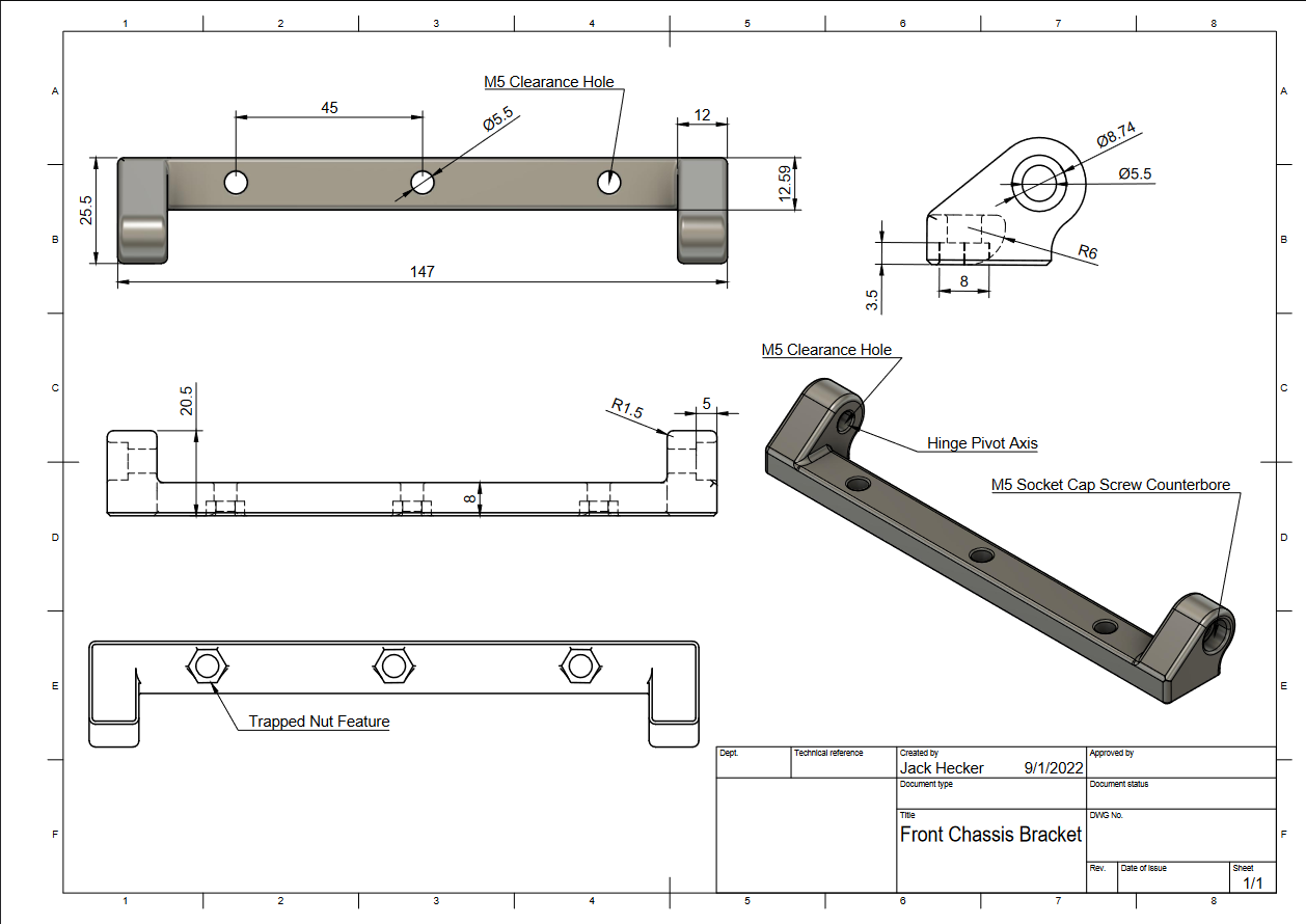
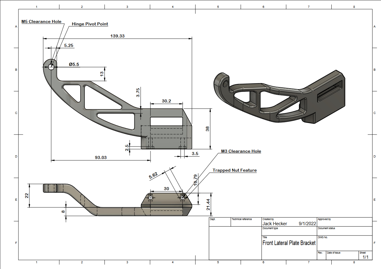
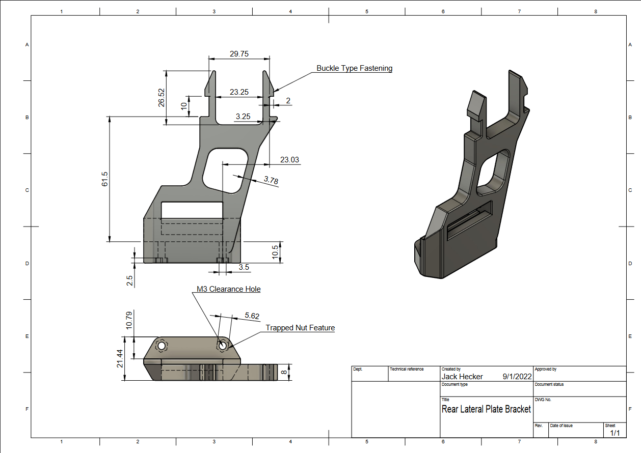
- All other installed 3D printed components were sourced from MakerBot Thingiverse and all credit goes to their original designers
New Car Mechanical Design
- Replacement car needed after fire damage destroyed the majority of components on the original car
- Replacement car provided by instructors
- Features similar component chassis design elements including hinge and modular locating points
Electrical Design
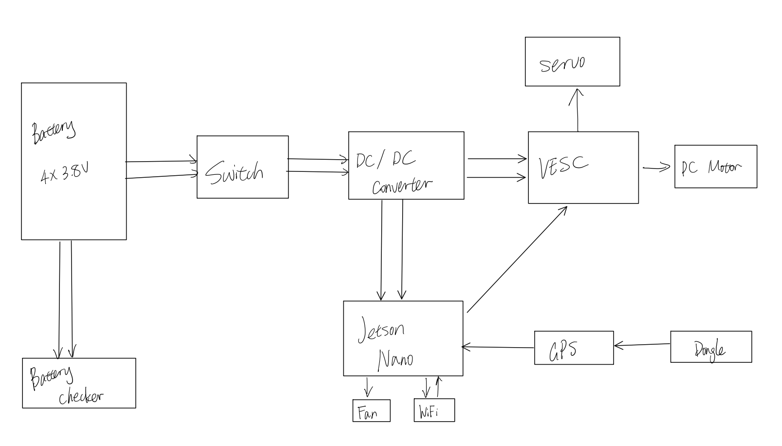
Autonomous Laps
Donkey Car autonomous laps
Data was collected using image inputs and controller outputs. For faster training, the model was trained on UCSD's GPU cluster. Link to our Donkey Car autonomous laps: https://drive.google.com/file/d/1RTPX5qU0wFP6MDB3UhvJxW1KVM96Jin2/view?usp=drivesdk
OpenCV and ROS2 autonomous laps
In order for our robot to only detect the yellow road lines, color calibration was done using the HSV model. The actuator was also calibrated to determine the different speeds and steering directions the car should go, given different situations. Link to our ROS2 autonomous laps: https://drive.google.com/file/d/1S99YGRlGTcsSg6vsi2YAWSbK7gCeC3Qe/view?usp=drivesdk
Final Project: Waypoint Finder
Project Description
Our project used GPS to find the current location of our robocar. Then, we created a python script to extract the longitude and latitude values provided by the GPS. Our goal was to move the robocar from one point to another and stop at specific longitude and latitude values, which we achieved.
Working With Ros2
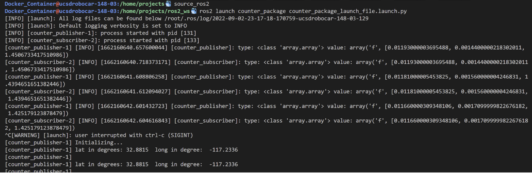
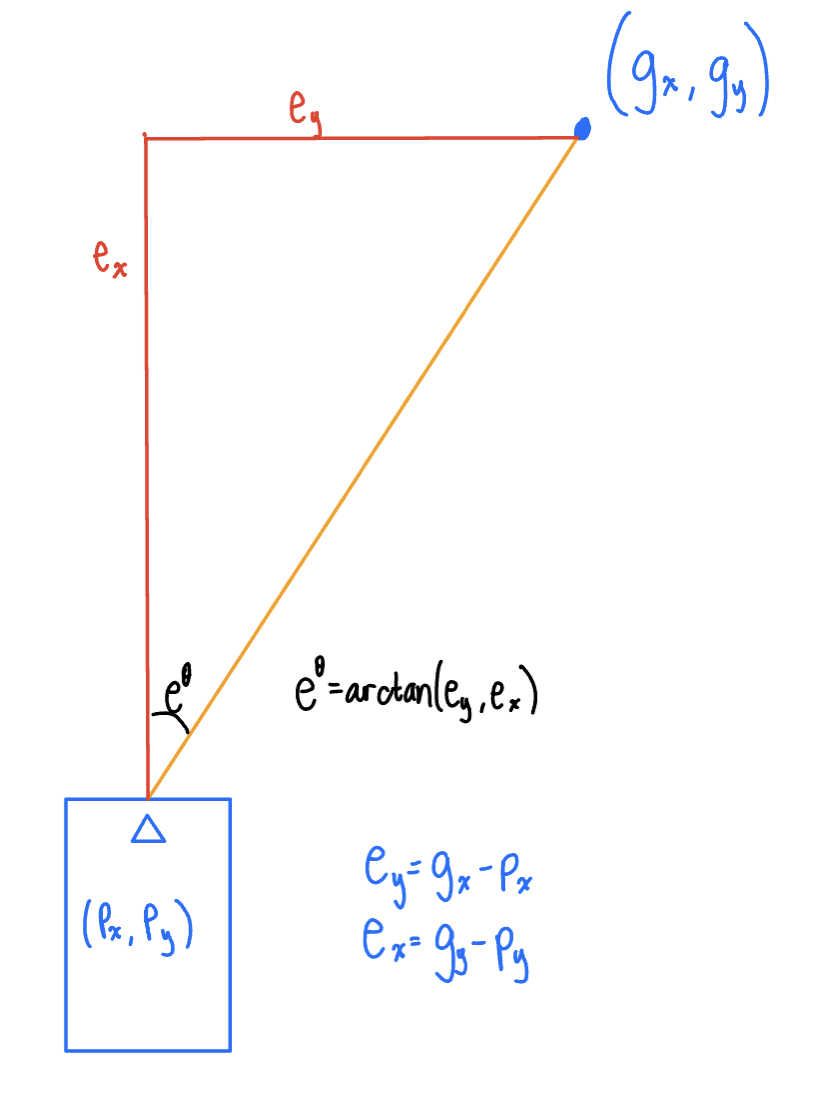
To determine where the car should go, we created a ROS driver to make the GPS accessible from ROS. We created a python script to output three elements: the difference in latitude and longitude from the desired coordinates and the angle the car must turn in order to face the desired coordinates (refer to the image on right). The gps_class_script.py file extracts the direction of latitude, time, latitude, and longitude from the GPGGA string which is stored into the NMEA_buff array. Given the current coordinates of the robot and the desired coordinates it is closest to, the difference in longitude and latitude is calculated and published along with the angle it must turn.
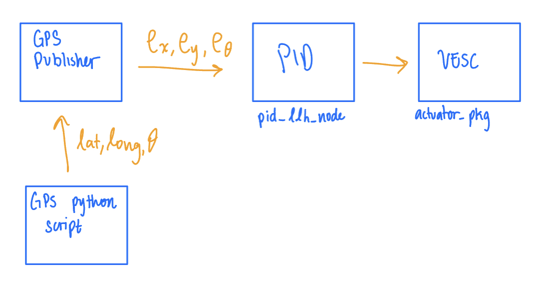
We created a publisher named counter_publisher.py (Disclaimer: We followed the counter_publisher.py file provided in the ROS2 guidebook and modified it to publish GPS values). This node publishes the values returned by the GPS python script.
The ~/ros2_ws_src_ucsd_robocar_hub2/ ucsd_robocar_control2_pkg/ ucsd_robocar_control2_pkg/ pid_llh_node.py node subscribes to counter_publisher. Here, we modified the speed constant.
Our main issue with the GPS was how often the given coordinates at the same position fluctuated. In the following video, despite starting the robot at different positions, the robot moves when it is not within the error threshold of the desired coordinates. The robot stops at approximately the same position with an error of ~2 meters. https://drive.google.com/file/d/1IcqUVptr2uf8PpWL5C5wHO-m0p86X5DY/view?usp=sharing
The following video is the most accurate the GPS was able to get. The blue box was our desired endpoint and the robot was able to stop within ~two feet. https://drive.google.com/file/d/1AxC33I-SJOpMyFPDWvYF5AZBztgAbCHY/view?usp=sharing
Code
Here is a link to our Docker image that mainly contains changes in the counter_package and ucsd_robocar_control2_pkg. Given more time, we would clean up our file directories. The script we used to obtain coordinates from the GPS can be found in ~ros2_ws/src/counter_package/counter_package/gps_submodule/gps_class_script.py.
https://hub.docker.com/r/wusx2021/ucsd_robocar
Disclaimer: We hope you can understand our code and that it works for you.
Challenges
| Challenge | Solution |
|---|---|
| Hardware uncertainties: car caught on fire | Replace nearly every component of our car. |
| Weak GPS signal inside the building. | Move our project outside. |
| GPS has a long response time. | Possible Solution: Obtain a better GPS (not feasible) |
| Jetson USB connection issues. | Constantly changing wires and ways of connection. |
Potential Improvements
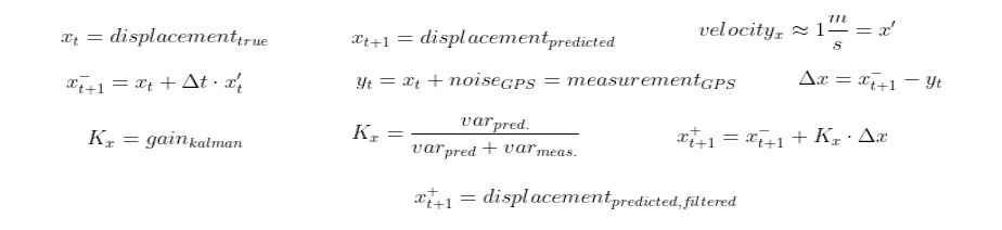
- Develop a Kalman filtering algorithm in the GPS node. This way, we would be able to estimate a more accurate location as an input to the motion controller.
- Use the IMU to obtain heading error and define the control regime relative to the car’s chassis.
Weekly Presentations
- Final project proposal: https://docs.google.com/presentation/d/1ly_FbgZF87KXT5ibsbR3lcxW28QueUECAe_OjDNcUDM/edit?usp=sharing
- Weekly progress: https://docs.google.com/presentation/d/1pJRHhM-LsijEPLNDkVAO9ESU2csp5Q1oWNYLZ9igETI/edit?usp=sharing
- Final presentation: https://docs.google.com/presentation/d/11hCKK3g83xjRlJJYe7qpxix_294h0_b73IaRavSreUo/edit?usp=sharing
References
We would like to express our gratitude to:
- Professor Jack Silberman
- TA Dominic Nightingale
- TA Ivan Ferrier
- ECE Makerspace
- Our Fantastic Classmates