2020WinterTeam2
Project Description and Objective
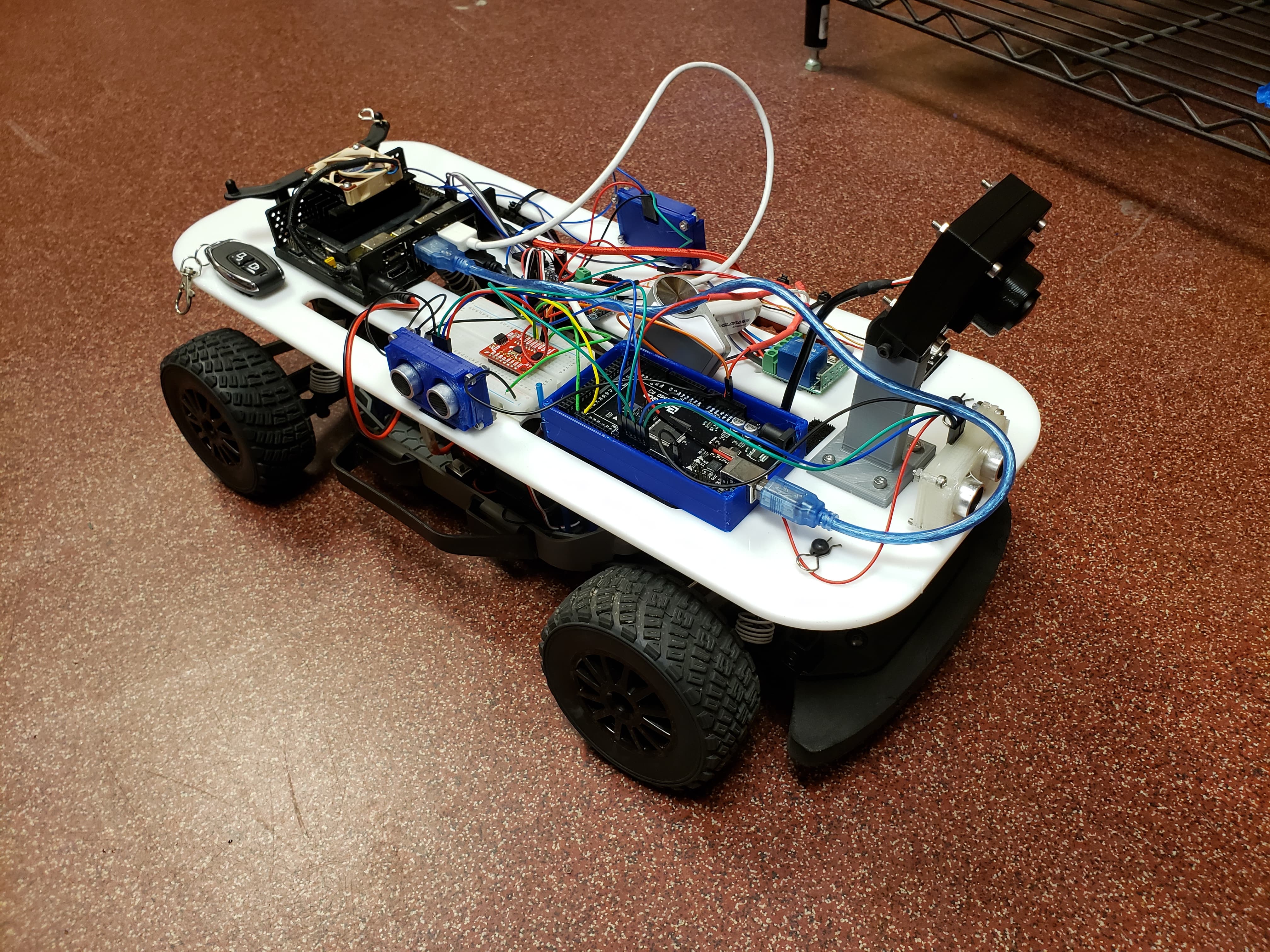
The goal of the project was to perform basic navigation tasks using an IMU, OpenCV, and ultrasonic sensors. After experimenting with GPS start and goal locations we decided to only use the IMU to drive in various shapes depending on different input trajectories. By doing that we want to provide an easy framework for future teams to build upon. In addition to driving based on the IMU data our aim was to include OpenCV object detection to be able to interact with various objects during the path of the car. We also set up ultrasonic sensors to be able to detect the distance to objects in front and on the sides of the car. We broke our overall goal down into 3 must-haves and 3 nice-to-haves:
Must haves:
- OpenCV camera obstacle recognition
- Ability to navigate in various patterns using IMU
- Ability to recognize and avoid obstacles while driving from point A to point B by using ultrasonic sensors and OpenCV
Nice-to-haves:
- Integrate lidar to be used in outdoor applications for must haves
- Obstacle avoidance optimization (e.g.: compute which distance appears shorter and turn in that direction to get around the obstacle)
- Ability to recognize different types of terrain and either avoid or modify speed accordingly
Team Members
Liam Engel, Mechanical Engineering B.S.
Jacinth Gudetti, Computer Engineering B.S.
Tanner Hanson, Mechanical Engineering B.S.
Hardware Setup and Schematics
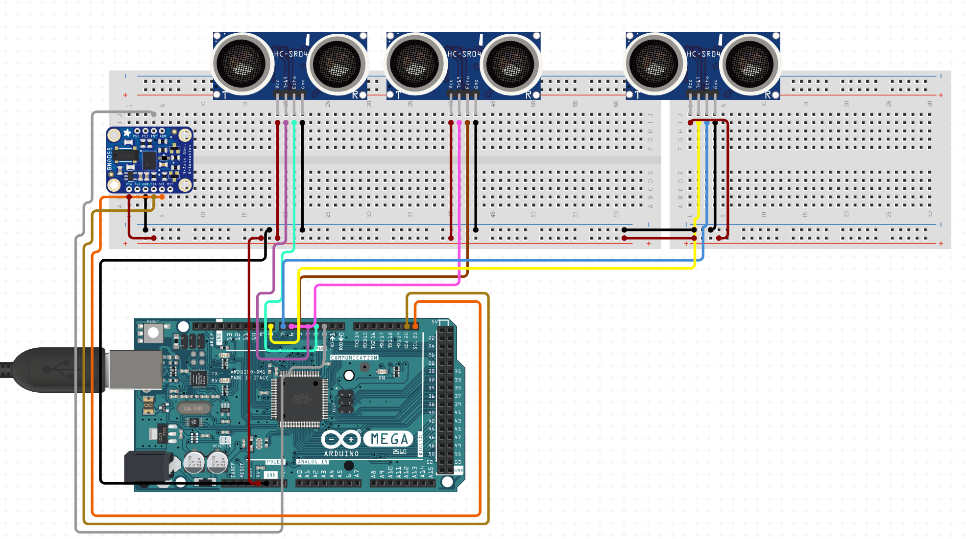
Team 2 utilized the following electrical components:
- Elegoo Mega 2560
- Three Ultrasonic Sensors
- BNO080 IMU
- GPS/GLONASS U-blox7 - a USB GPS
- Jetson
Mechanical Components:
We have included the following Mechanical Components in our GitHUB for use by future groups:
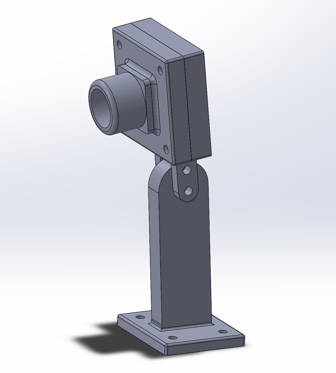
- Camera Mount: Our team went through several iterations of camera mounts before settling on a design that proved to be simple yet efficient. Our camera mount differs from the mounts of other groups in that our mount was not as tall as those of other groups since we did not see a reason for it to be so high.
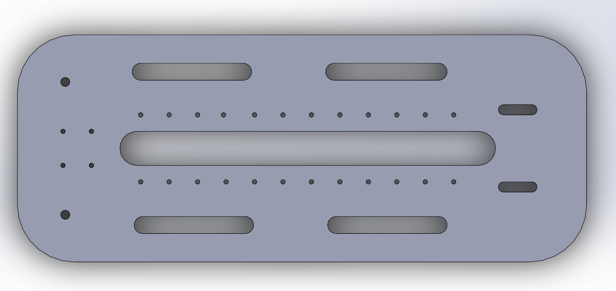
- Base Plate: We designed the base plate so that it would be both aesthetically pleasing in appearance and versatile in utility. We designed the plate to be compatible with 4 mm screws. Our design was laser cut from a quarter inch piece of acrylic.
We found the following components online and have attached the corresponding links to their 3D models below:
- Jetson Case at https://www.thingiverse.com/thing:3518410
- Ultrasonic Sensor Case at https://www.thingiverse.com/thing:1415951
- Arduino Mega Case at https://www.thingiverse.com/thing:2709747
IMU Implementation
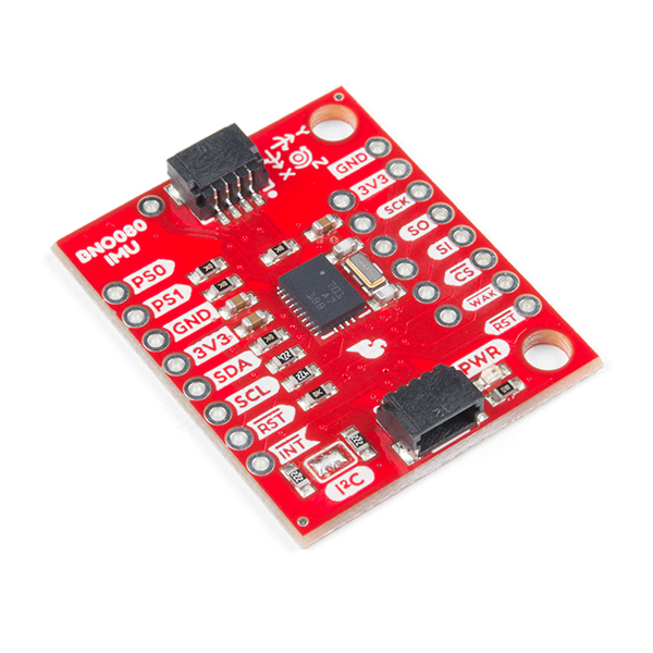
The adjusted goal of our project was to drive the robot car based on an IMU only. The Inertial Measurement Unit (IMU) utilizes accelerometers, magnetometers, and gyroscopes to determine a system’s orientation, acceleration rate, and angular rate when the IMU is installed on the system. This data is sufficient to make the robot car drive in certain patterns. The BNO 080 proved to be highly accurate and responsive. We hope to provide a framework for future teams to be able to easily include the IMU and build upon that e.g. when implementing GPS, path planning and more sophisticated maneouvering around obstacles.
Hookup Guide
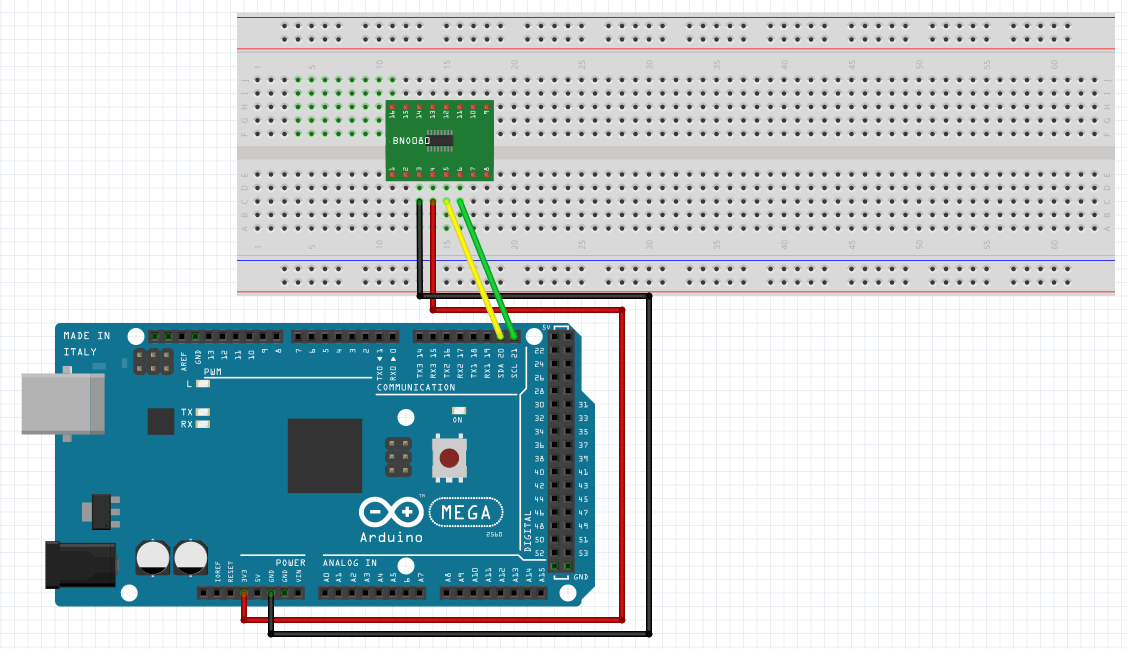
We connected the IMU to the Arduino Mega 2560 using the following wiring:
- 3V3 to Power
- GND to GND
- SCL to default SCL on Arduino
- SDA to default SDA on Arduino
A hookup guide and additonal useful information can be found at the following link (previous model BNO 055). [1]
Getting data from the IMU
The following library on Sparkfun proved to be very useful and extensive.[2] It includes information on the IMU and Arduino code for various applications. It is a good idea to download the Library and then follow the instructions in the various examples on the page that include:
- Rotation Vectors
- Accelerometer
- Gyro
- Magnetometer
- and many more
The code can directly be copied in Arduino. For our purposes it was sufficient to use Example 1 (Rotation vectors). The code gives rotation vectors around the x,y and z-axis that can be transformed into heading angles (i.e.: roll, pitch and yaw). In the context of our project we wanted to use the rotation vector around the z-axis out of the car plane to get the heading angle. The arduino program gives the vector in quaternions (i,j,k) that can be transformed to euler angles [-pi to pi] using adjusted C++ code from the linked page.[3]. It is also included in our Github-Page (Arduino Code).
Logical setup: Driving with the IMU
Driving with the IMU is based on the following logical schematic.
The logical setup consists of a controller with two inputs and one output. The two inputs are the actual current heading that is given by the IMU and the desired heading. This desired heading will be discussed in the next section. We used a proportional controller with gain K (a good first guess for the controller gain is maxsteering/π as it guarantees maximum steering for maximum error). The steering command that is proportional to the error is then transmitted to the servo that steers the wheels. Since the steering is normalized ([-1,1]) right or left turn based on shortest distance can easily be achieved. Issues occur when the shortest path from actual heading to desired heading includes a singularity (jump from -π to π). E.g. when the actual angle is 170 degrees and the desired angle is -170 degrees the car would take the longer turn instead of the shorter one. A good objective for a group building on this work would be to tackle this problem.
Possible trajectories
A good way to start is to drive a straight line by giving a constant desired angle. Once that is achieved more sophisticated trajectories can be achieved like a square a circle or a zigzag line. Also the trajectory can serve as an interface to a GPS that gives the desired heading that is then compared to the actual heading given by the IMU. An example for the implementation of driving a square would be the following sequence of desired angles: [5°, 95°, -175°, -85°]. These angles can turned into a trajectory using interpolate functions in Python.
Issues and ideas
After setting up the IMU we encountered issues with keeping the robot in a straight line as it tended to overshoot. Different control gains and types of controllers would need to be investigated. Another idea is to give a certain tolerance around the desired angle where the current angle is accepted as the correct angle.
Software Design and OpenCV Implementation
Ultrasonic Filtering
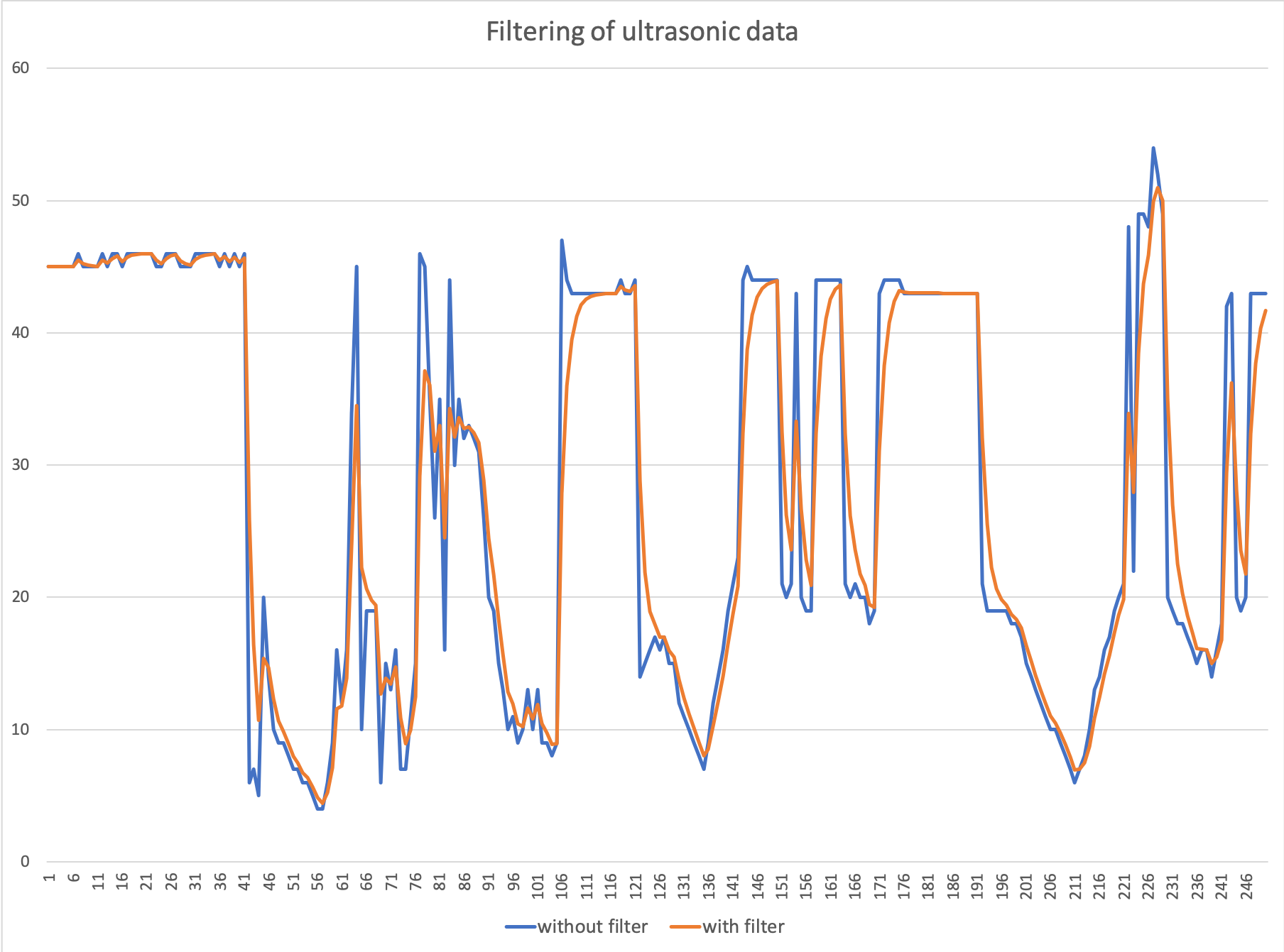
When we first began to use the ultrasonic sensors, we noticed that it was common for the ultrasonic sensors to produce data that was wildly inaccurate. There were many outliers and out of bounds values. This could especially be seen when objects were turned or had specific surfaces (e.g. a water bottle). To combat this, we developed a filter that would parse out this inaccurate data. As such, we developed a filter that had the following layout:
y_new=(α)*(y_old)+(1-α)*(sensor_reading)
y_old=y_new
This is a first-order discrete time filter. In addition to this filter we also cut unreasonably large values. We initialized y_old as 0 and found through our trials using sampled data that an α-value of 0.5 was ideal. Since the y_old value was initialized as 0, it generally took a couple of iterations to get accurate sensor data. We have included this code in our GitHUB for future teams to use and modify based on their needs. The following graph shows a result of the filtering with data we collected.
OpenCV Shape Detection
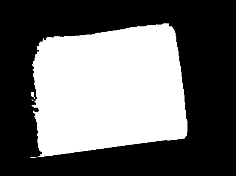
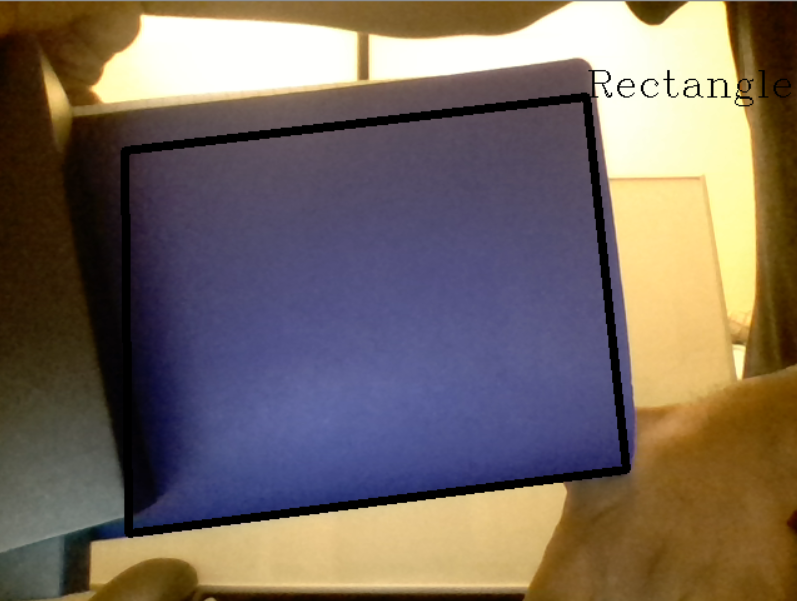
For OpenCV, we used HSV filters and contours to allow our camera to detect shapes. I highly recommend going through Pysource's tutorial [4]
First we specify lower and upper bounds for hue, saturation, and value. In our case, we manually adjusted these bounds until we reliably detected only purple shapes. Once this is done, we create a mask using these values and use the erode function to remove boundaries of the foreground object.
Now that the mask is set up, we can draw lines on the object. For this purpose, we specified a contour area of over 400 pixels to reduce insignificant objects at a distance, and use drawContours() to draw lines along the boundaries of the shape. If the number of lines in this contour is 3, it is a triangle, if it is 4, then it is a rectangle.
Within these shape checks, a global variable relating to the vehicle is set and this variable is used to determine whether it is appropriate to stop the vehicle.
Overall program outline
To run this program, we utilize a custom manage and planner python files, specifically pseudo_manage.py and pseudo_planer.py (the latter is in the gps_parts directory) along with a custom IMU parts file imu.py to get the IMU reading from the Arduino.
Use this command to run the code:
python pseudo_manage.py
imu.py: reads data from the IMU which is linked to the Arduino which communicates to the Jetson at serial port ttyACM0 (use 'dmesg | grep tty' to check what your USB port is named)
pseudo_planner.py: which performs calculates to direct the car given the output from imu.py and the desired heading variable. With the addition of the cvcam part, it will make the car stop when cvcam.py returns a stop_cmd value of true.
pseudo_manage.py: is a modified manage.py that includes a call to the IMU part.
Note: We left the GPS parts included by Team 5 intact as doing so would allow us to experiment with GPS later on down the road. For initial testing, please connect the U-blox7 GPS module
We largely based our work on 2018 Fall Team 5's work so please check out their work if you need assistance integrating IMU with GPS for the most accurate budget GPS navigation setup. Our pseudo_manage.py and pseudo_planner.py were largely based on Team 5's ultra_gps_manage.py and ultra_planner.py from R.O.B.O.B.O.I.
Results
File:Video-1584058620.mp4 What we accomplished:
- Successfully set up IMU with Arduino and made heading angle available on Jetson
- Enabled car to drive and navigate based on IMU
- Made OpenCV capable of recognizing certain shapes and stopping
- Ultrasonic sensors are configured to work in conjunction with OpenCV to determine how far away obstacles are away
Where we struggled:
- Adjust code so that car doesn’t overshoot (didn’t achieve to make it drive in a straight line), Idea: have tolerance threshold where heading angle is assumed to be correct and car goes straight, try different controllers and gains
- Include GPS into the planning of the trajectory (hardware issues)
- Include ultrasonic sensors on the side into our program
- Circulation around objects
Lessons Learnt and Next Steps
We learned a lot while working on this project but some lessons that really stood out were:
- SIMPLIFICATION (Focus on implementing one part really well)
- Starting with IMU and implementing GPS later seems to be a good option
- BNO 080 is very responsive and accurate: groundwork for future projects surrounding navigation
- Singularity in heading angle out of IMU is an issue (as described in IMU section)
We would recommend the following next steps for future teams who wish to build upon our work:
- Try to drive various trajectories like circles (maybe write a name using colour? that would be cool! ;))
- Implement GPS (account for variation between heading from GPS and IMU)
- Use IMU to maneuver around obstacles
- Build on foundation to fully focus on interacting with obstacles using OpenCV and ultrasonic sensors